The following diagrams explain each part of the BlackVue dashcam.
Main box #
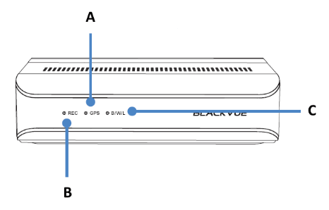
A) GPS LED:
![]() : Lights blue when GPS is on.
: Lights blue when GPS is on.
![]() : Blinks blue slowly when GPS is turning off.
: Blinks blue slowly when GPS is turning off.
B) Recording LED:
![]() : Lights orange in normal mode.
: Lights orange in normal mode.
![]() : Lights red when (i) an event is being recorded (impact detected), or (ii) manual recording has started.
: Lights red when (i) an event is being recorded (impact detected), or (ii) manual recording has started.
![]() : Lights green in parking mode when motion is detected.
: Lights green in parking mode when motion is detected.
C) Bluetooth/ Wi-Fi/ LTE LED:
![]() : Lights yellow when LTE is connected.
: Lights yellow when LTE is connected.
![]() : Lights white when Wi-Fi is connected.
: Lights white when Wi-Fi is connected.
![]() : Blinks yellow slowly when Bluetooth is paired.
: Blinks yellow slowly when Bluetooth is paired.
![]() : Blinks yellow quickly when Bluetooth is in pairing mode.
: Blinks yellow quickly when Bluetooth is in pairing mode.

A) Lock
SOS Button #
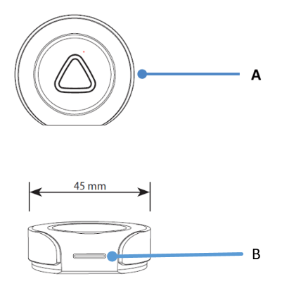
A) Emergency Button
B) LED indicator:
![]() : Blinking green light when inserting battery for the first time.
: Blinking green light when inserting battery for the first time.
![]() : Blinking green light when button is pressed.
: Blinking green light when button is pressed.
![]()
![]() :Blinking red and green lights when connecting to main unit.
:Blinking red and green lights when connecting to main unit.
![]() : Blinking red light when voltage is low.
: Blinking red light when voltage is low.
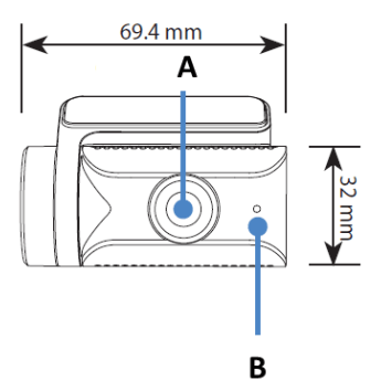
Front Camera #
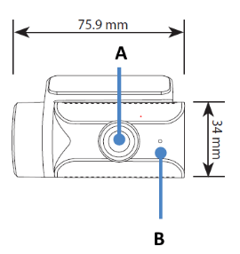
A) Camera Lens
B) Front security LED:
![]() : Lights on during (i) normal mode, (ii) an event is being recorded (impact detected), (iii) manual recording has started, or (iv) motion is detected in parking mode.
: Lights on during (i) normal mode, (ii) an event is being recorded (impact detected), (iii) manual recording has started, or (iv) motion is detected in parking mode.
![]() : Blinks slowly during parking mode motion detection standby.
: Blinks slowly during parking mode motion detection standby.
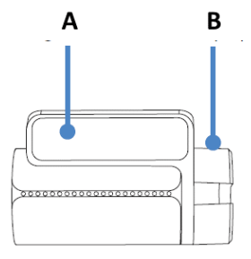
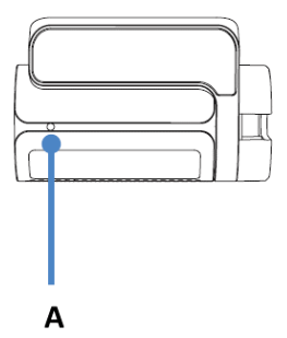
A) Mounting bracket
B) Tamperproof case

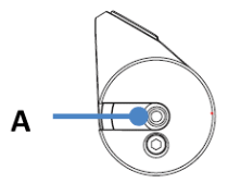
A) Main unit connection port
B) Tamperproof case
Rear Camera #
A) Camera Lens
B) Front security LED:
![]() : Lights on during (i) normal mode, (ii) an event is being recorded (impact detected), (iii) manual recording has started, or (iv) motion is detected in parking mode.
: Lights on during (i) normal mode, (ii) an event is being recorded (impact detected), (iii) manual recording has started, or (iv) motion is detected in parking mode.
![]() : Blinks slowly during parking mode motion detection standby.
: Blinks slowly during parking mode motion detection standby.

A) Mounting bracket
B) Tamperproof case

A) Main unit connection port
B) Tamperproof case
Rear Infrared Camera #

A) Tamperproof case
B) Camera lens
C) Illumination sensor
D) IR LED
A) Rear Security LED
A) V Out (Main unit connection port)
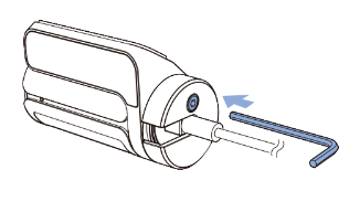
Removing and attaching the tamperproof case on front, rear and Interior IR camera #
A) Use the Allen wrench to untighten the screw and take out the bracket.

B) Plug the camera connection cable to the camera. Align the screw hole of the tamperproof case and the camera. Tighten the screw to hold the tamperproof case just enough for the body of the camera to rotate.
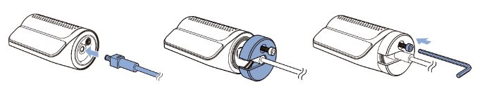
C) After attaching the camera to its respective position (refer to the installation guide for the recommended position of each camera) fully tighten the screw to ensure angle of the lens is fixed in place.
Rear truck Camera #
A) Illumination Sensor
B) Angle lock screw
C) Camera lens
D) Main unit connection port
E) IR LED
F) External mounting bracket


