🔗 Installation Video : Hardwire Kit(HWK-5FT) Installation Guide
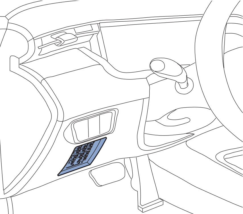
Step 1: Locate the Fuse Box #
-
In most vehicles, the fuse box is located under the driver’s side dashboard, near the steering column, or inside the glove compartment
-
Refer to your vehicle’s user manual to find the exact location.
“Typical Fuse Box Locations in Passenger Vehicles”
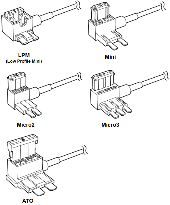
Step 2: Identify the Fuse Type and Select the Correct Holder #
-
Fuse types vary by vehicle. Remove one of the existing fuses and compare it with the supplied fuse holders.
-
Supported types: Micro2 / Micro3 / Mini / ATO / LPM
-
Use the fuse holder that matches the shape and size of the original fuse.
“Match the fuse type by shape and pin spacing”
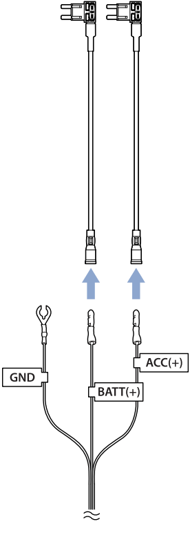
Step 3: Connect the Hardwire Power Cable #
Wire Functions

| Wire | Wire Color | Description |
|---|---|---|
| ACC (+) | Red | Connects to a fuse slot that receives power only when the ignition is ON. |
| BATT (+) | Yellow | Connects to a fuse slot that receives constant power, regardless of ignition status. |
| GND (-) | Black | Connects to a clean, unpainted metal bolt on the vehicle chassis for grounding. |
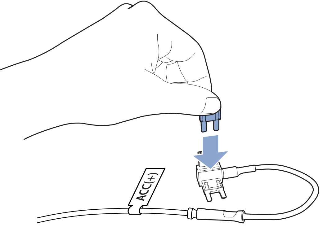
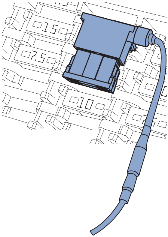
● Connecting the Fuse Tap to the Hardwire Cable #
-
Each ACC and BATT wire is pre-configured with a plug-and-play fuse tap connector — no crimping tool is required.
-
Simply select the fuse tap type that matches your vehicle’s fuse slot (Micro2, Micro3, Mini, ATO, or LPM).
-
Plug the corresponding wire (ACC and BATT) into the selected fuse tap.
-
Ensure the connection is firm and fully inserted.
📋 TIP: Do not connect both wires to a single fuse tap. ACC and BATT must be installed in separate fuse slots.
● Identifying ACC and BATT Fuse Slots #
To determine the correct fuse slots in your vehicle:
-
Use a multimeter or test light to check voltage at each slot:
-
ACC: 0V when ignition is OFF, 12V+ when ON.
-
BATT: 12V+ at all times, regardless of ignition.
-
-
Common labels for ACC fuses: ACC, IGN, Radio, Audio, Power Outlet
-
Common labels for BATT fuses: Dome, Clock, ECU, Memory, Hazard
📋 TIP: Refer to your vehicle’s fuse box diagram, located on the fuse panel cover or in the owner’s manual.
● Inserting Fuses into the Fuse Tap #
-
Each fuse tap is pre-installed with a 3A or 5A fuse to protect the dashcam circuit.
-
Into the empty slot of the fuse tap, insert the original fuse removed from your vehicle.
-
This allows the factory circuit to continue functioning normally, while also powering the dashcam.
⚠️ Make sure both fuses are fully seated and the fuse tap blades are securely inserted into the fuse slot.
●Inserting the Fuse Tap into the Vehicle’s Fuse Box #
Once you have installed both fuses (the new 3A/5A fuse and the original fuse) into the fuse tap:
-
Insert the fuse tap labeled ACC (red wire) into the fuse slot identified as switched power (ACC).
-
This is the slot that only receives power when the ignition is turned ON.
-
-
Insert the fuse tap labeled BATT (yellow wire) into the fuse slot identified as constant power (BATT).
-
This slot should supply 12V at all times, regardless of ignition status.
-
-
Press each fuse tap firmly and fully into the corresponding slot in the fuse box.
-
You should feel a slight resistance and then a secure fit as the blades seat properly.
-
📌 TIP: Make sure the fuse tap orientation follows the correct current flow direction.
Some vehicles may require the fuse tap to be rotated 180°, depending on the fuse box layout. If in doubt, check with a multimeter or refer to your vehicle manufacturer’s documentation.
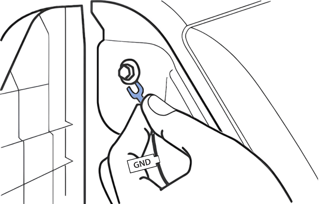
● Ground Wire Connection #
-
Attach the GND (black) wire’s ring terminal to a metal bolt on the vehicle chassis.
-
Ensure the bolt is clean, unpainted, and free of rust or insulation for proper grounding.
-
Tighten the connection securely.
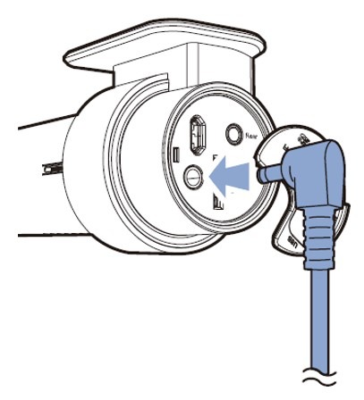
Step 4: Connect to Dashcam and Verify Operation #
-
Plug the hardwire cable into the dashcam’s power port (DC-in).
-
Start the engine to check if the dashcam powers on normally.
-
Turn the ignition OFF to verify that the dashcam remains powered—this indicates Parking Mode is working correctly.
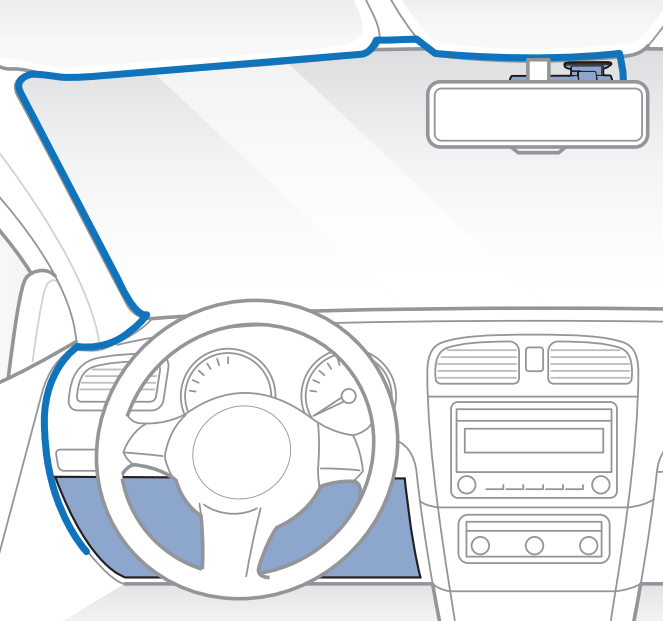
Step 5: Tidy Up the Cables and Adjust the Dashcam Angle #
Cable Management #
-
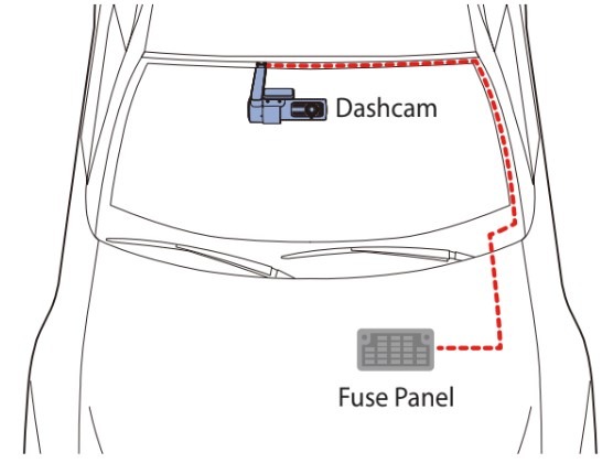
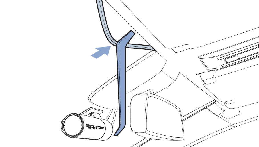
Route the power cable along the vehicle’s headliner, A-pillar, and under the dashboard for a clean and hidden installation.
-
Use the included pry tool to gently tuck the cable without damaging interior panels.
-
Secure the cable with cable clips or zip ties where needed to keep it away from pedals, gear levers, and airbags.
-
Avoid routing the cable across moving parts or areas that may interfere with airbag deployment or the driver’s line of sight.
Adjust Dashcam Viewing Angle #
-
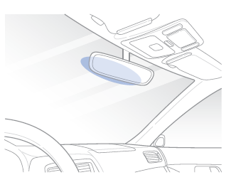
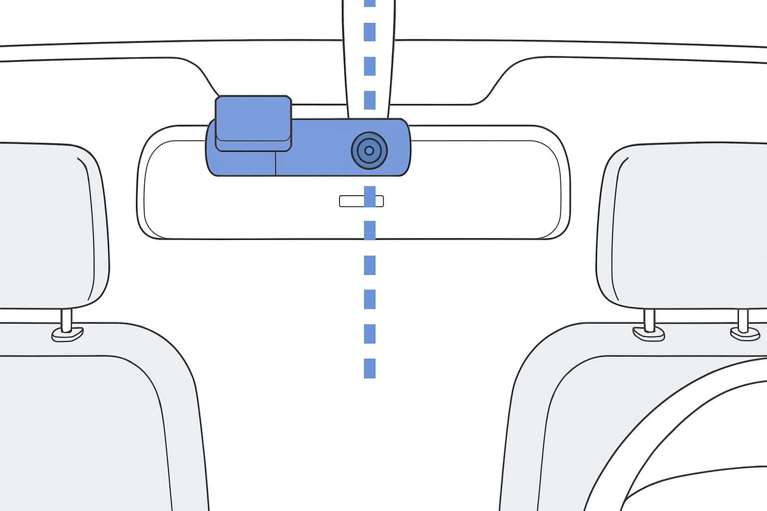
Mount the dashcam near the center of the windshield or just behind the rearview mirror.
-
Adjust the lens so that roughly 60% of the screen shows the road and 40% shows the sky or dashboard.
-
Connect to the dashcam using the BlackVue App (via Wi-Fi Direct or Cloud) and use the Live View feature to check and adjust the actual camera angle.
-
Ensure the lens is not obstructed by tinted film, stickers, or windshield wipers.
📋 TIP: After setting the angle, firmly tighten the mount to prevent it from moving while driving.
📋 Final Check #
-
Insert the fuse taps into the identified ACC and BATT fuse slots securely.
-
Tighten and confirm the GND connection is properly grounded.
-
Double-check all wiring connections before turning on the ignition.
-
Make sure cables are not obstructing any moving parts, pedals, or airbags.
📌 Additional Tips #
-
For added battery protection during long-term parking, consider using BlackVue B-130A or an external battery pack
🔗 Link : FAQs – Hardwire Kit


